Description
- Covers Allison TT, TTB, TRT 2001 Series Powershift Transmission
- TT 2221-1
- TTB 2221-1
- TT 2421-1
- TTB 2421-1
- TRT 2211-3
- TRT 2411-3
- TRT 2221-1
- TRT 2421-1
- TRT 2221-3
- TRT 2421-3
- 221 pages
- Instant PDF Download
- Searchable, printable
- Compatible with Windows/Mac/Tablet
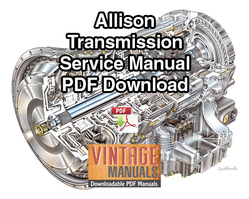
This Repair Manual describes the mechanical operation, maintenance, and overhaul procedures for Allison TT, TTB, TRT 2001 Series Powershift transmissions. It includes detailed OEM specs, illustrations and service procedures to guide the mechanic with correctly servicing, overhauling and troubleshooting the Allison TT, TTB, TRT 2001 Series Powershift transmissions listed to the manufacturer’s specifications. The manual is available in a convenient downloadable PDF file.
Allison TT, TTB, TRT 2001 Series Powershift Transmission Repair Manual Contents:
- GENERAL INFORMATION
- DESCRIPTION AND OPERATION
- PREVENTIVE MAINTENANCE
- GENERAL OVERHAUL INFORMATION
- DISSASSEMBLY OF TRANSMISSION INTO SUBASSEMBLIES
- REBUILD OF SUBASSEMBLIES
- ASSEMBLY OF TRANSMISSION FROM SUBASSEMBLIES
- WEAR LIMITS AND SPRING DATA
- TORQUE SPECIFICATIONS
- TABLES
- FOLDOUTS / SCHEMATICS

1-1. SCOPE OF MANUAL
a. Coverage
b. Illustrations
c. Maintenance Information
1-2. SUPPLEMENTARY INFORMATION
1-3. ORDERING PARTS
a. Transmission Nameplate
b. Parts Catalog
1-4. DESIGN FEATURES
a. Model Differences
b. Mounting, Input Drive
c. Twin-Turbine Torque
Converter
d. Range Gearing, Clutches
e. Transfer Gears
f. Output Shafts
g. Converter-driven Power
Takeoff
h. Output-driven Power
Takeoff
i. Internal Brake.
j. Accessory Drive Pad
k. Oil Pump
1. Control Valve Body
Assembly. • • 1-4
m. Parking Brake •••••• 1-4
n. Oil Filter, Cooler. • 1-4
OPERATING INSTRUCTIONS
a. Related to Vehicle. •
b. Range Selection • • •
c. Changing Direction of
Travel. . . . . . . .
d. Clutch Cutoff Control .
e. Inching Control .
f. Output Disconnect . . .
g. Towing. . . . . . . .
h. Temperatures, Pressures
SPECIFICATIONS, DATA. . . .
Section 2. DESCRIPTION AND OPERATION
2-1. SCOPE . . . . . . . . . . . . 2-1
2-2. GEARING, CLUTCHES, HYDRAULIC
SYSTEMS, TORQUE PATHS •••• 2-1
2-3. POWER TAKEOFF (TT)
a. Converter-driven PTO. • • 2-1
b. Output-driven Power
Takeoff • • • • • • • • • 2-1
2-4. IMPLEMENT PUMP, ACCESSORY
DRIVE PADS
a. Implement Pump Drive
Pad • • • • • • 2-1
b. Accessory Drive Pad ••• 2-1
2-5. OIL PUMP. • • • •••• 2-3
2-6. INTERNAL BRAKE (TTB)
Brake Components.
Brake Operation •
PARKING BRAKE ••• 2-3
CONTROL VALVE BODY ASSEMBLY
a. Control Valve Body •••• 2-4
b. Main-pressure Regulator,
Selector Valves • • • •• 2-4
c. Clutch Cutoff Valve ••• 2-4
d. Inching Control Valve •• 2-4
HYDRAULIC SYSTEM (All Models)
System Functions.
System Schematics
HYDRAULIC SYSTEM (TT, TTB)
a • Oil Pump, Filter Circuit. 2-5
b. Main-pressure Regulator
Valve, Converter-in
Circuit . . . . . . . . . 2-5
c. Torque Converter. . . . . 2-5
d. Converter-out, Cooler,
Lubrication Circuit . . . 2-5
Copyright 1984 General Motors Corp. i
TABLE OF CONTENTS (CONT)
Para Page
e. Clutch Cutoff Valve
Circuit • • • • • • 2-5
f. Inching Control Valve
Circuit • • • • • • • • • 2-9
g. Manual Selector Valve
Circuit ••••••••• 2-9
h. Trimmer Circuit • • • • • 2-9
i. Internal Brake Coolant
Lubrication Circuit • • • 2-10
2-11. HYDRAULIC SYSTEM (TRT 2221,
TRT 2421)
a. Oil Pump, Filter Circuit. 2-10
b. Main-pressure Regulator
Valve, Converter-in
Circuit • • • • • • • • • 2-10
c. Torque Converter ••••• 2-10
d. Converter-out, Cooler,
Lubrication Circuit • 2-10
e. Clutch Cutoff Valve
Circuit • • • • • 2-10
f. Inching Control Valve
Circuit ••••••••• 2-10
g. Manual Selector Valve
Circuit • • • • • • 2-10
h. Trimmer Circuit • • • 2-12
2-12. HYDRAULIC SYSTEM (TRT 2211,
TRT 2411)
2-13.
a. Oil Pump, Filter Circuit. 2-12
b. Main-pressure Regulator
Valve, Converter-in
Circuit • • • • • • • • • 2-12
c. Torque Converter ••••• 2-12
d. Converter-out, Cooler,
Lubrication Circuit ••• 2-12
e. Clutch Cutoff Valve
Circuit • • • •
Inching Control
Circuit ••••
Manual Selector
Circuit ••••
Trimmer Circuit
Valve
Valve
TRANSMISSION TORQUE PATHS
a. Component Functions • • • 2-14
b. Cross-section
Illustrations • • • 2-15
c. Torque Converter,
Freewheel Clutch. • • 2-16
Para Page
2-14. CONVERTER GEARING TO FORWARDAND-
REVERSE SUN GEAR–
TORQUE PATH
a. First Turbine • • • • 2-17
b. Second Turbine. • •••• 2-19
2-15. TT, TTB 2221-1, 2421-1
TORQUE PATHS
a. Neutral and Power
Takeoff • • • • •
b. Forward-1 (low-range) •
c. Forward-2 (high-range).
d. Reverse Range • • • • •
2-16. TRT 2221-1, 2421-1 TORQUE PATHS
a. Neutral and Power
Takeoff • • • • • • • • • 2-24
b. Forward-1 • 2-25
c. Forward-2 • 2-26
d. Reverse-1 • • 2-26
e. Reverse-2 • • • • • 2-26
2-17. TRT 2221-3, 2421-3 (Underdrive
Models) TORQUE PATHS
a. Neutral • • •••• 2-27
b. Forward-1 • • •••• 2-28
c. Forward-2 • 2-29
d.
e.
Reverse-1 •
Reverse-2
2-18. TRT 2221-3, 2421-3 (Overdrive
Models) TORQUE PATHS
a. Neutral • • • • • • 2-31
b. Forward-1 • • • • • 2-31
c. Forward-2 • 2-31
d. Reverse-1 • 2-32
e. Reverse-2 •••••• 2-33
2-19. TRT 2211-3,
a. Neutral
2411-3 TORQUE PATHS
. . • . . . . 2-34
b. Forward • • 2-34
c. Reverse • 2-35
Section 3. PREVENTIVE MAINTENANCE
3-1. SCOPE • • • • • • • • • • • • 3-l
3-2. PERIODIC INSPECTIONS,
CLEANING
a. Inspecting Exterior ••• 3-1
b. Cleaning Breather • • • • 3-1
3-3. OIL CONTAMINATION
a. Examine at Oil Change •• 3-1
b. Coolant Leakage • • 3-1
c. Metal Particle. • • • • • 3-1
d. Auxiliary Filter ••••• 3-2
3-4. CHECKING OIL LEVEL
a. Cold Check (check plug) • 3-2
b. Hot Check (check plug) •• 3-2
c. Cold Check (dipstick) •• 3-3
d. Hot Check (dipstick) ••• 3-3
3-5. MAINTENANCE INTERVALS
a. Frequency • • • • • • 3-3
b. Oil and Filter Change • • 3-3
3-6. CHANGING OIL, FILTER
a. Draining Oil. • 3-3
b. Refilling Oil System. • • 3-3
3-7. BLEEDING INTERNAL BRAKE
(TTB Models) ••••••••• 3-3
3-8. PRESSURES, TEMPERATURES ••• 3-4
3-9. LINKAGE CHECKS, ADJUSTMENTS
a. See Vehicle Manual
Instructions. • • • • • • 3-4
b. Selector, Inching
Linkage • • • • • • • 3-5
c. Front Output Disconnect • 3-5
d. Parking Brake (external,
mechanical) • • • • 3-5
3-10. TRANSMISSION STALL TEST
a. Purpose •
b. Procedure •
c. Results ••
3-11. PRESERVATION, STORAGE
a. Storage, New
Transmissions • • • • • • 3-6
b. Preservation Methods ••• 3-6
c. Storage, 1 Year–Without
Oil • • • • • • • • • • • 3-6
Para Page
d. Storage, 1 Year–With
Oil • • • • • 3-7
e. Restoring Units to
Service • • • • 3-7
3-12. FLANGE RETAINER • 3-7
3-13. TROUBLESHOOTING
a. Importance of
Troushooting ••••••• 3-8
b. Troubleshooting Table • • 3-8
Section 4. GENERAL OVERHAUL
INFORMATION
4-1. SCOPE • ••• 4-1
4-2. MODEL CHANGES •••• 4-1
4-3. TOOLS, EQUIPMENT
a. Special Tools • 4-1
b. Mechanic’s Tools, Shop
Equipment • • • 4-1
4-4. REPLACEMENT PARTS
a. Ordering Information. • • 4-4
b. Parts Normally Replaced • 4-4
4-5. CAREFUL HANDLING ••• • 4-4
4-6. CLEANING, INSPECTION
a. Dirt-free Assembly. • 4-4
b. Cleaning Parts •••••• 4-4
c. Cleaning Bearings •••• 4-4
d. Inspecting Bearings • 4-5
e. Keeping Bearings Clean. • 4-5
f. Inspecting Cast Parts,
Machined Surfaces • • • • 4-5
g. Inspecting Bushings,
Thrust Washers •••••• 4-5
h. Inspecting Oil Seals,
Gaskets • • • • • • • • • 4-6
i. Inspect·ing Gears. • • • • 4-6
j. Inspecting Splined Parts. 4-6
k. Inspecting Clutch Plates. 4-6
1. Inspecting Threaded
Parts • . • • • • • • • • 4-6
m. Inspecting Snaprings ••• 4-6
n. Inspecting Springs •••• 4-6
Copyright 1984 General Motors Corp. iii
TABLE OF CONTENTS (CONT)
Para Page
o. Inspecting Seal Contact
Surfaces. • • • • • • • • 4-7
p. Inspecting Swaged,
Interference-fit Parts •• 4-7
q. Inspecting Balls in
Clutch Pistons. 4-7
r. Inspecting Pump Gears •• 4-7
4-7. ASSEMBLY PROCEDURES
Clutches, Pistons •• 4-7
Parts Lubrication • • 4-7
External Pipe Plugs,
Hydraulic Fittings •••
Oil-soluble Grease •••
Sealing Compounds, Nonsoluble
Greases ••••• 4-7
Metal-Encased Oil Seals • 4-7
Interference-fit Parts. • 4-8
Sleeve-type Bearing • • • 4-8
Bearings (ball or roller) 4-8
REMOVING, INSTALLING
TRANSMISSION
a. Drain Oil • • • • • 4-8
b. Check Linkages, Lines •• 4-8
c. Remove, Clean
Transmission. • • • 4-8
d. Lifting • • • • 4-8
e. Reconnect at
Installation. • 4-8
4-9. TIGHT-FIT FLANGES
a. Removal of Flanges 4-9
b. Installation of Flanges • 4-9
4-10. WEAR LIMITS, SPRING DATA
a. Wear Limits Inspection. • 4-10
b. Spring Inspection • • 4-11
4-11. TORQUE SPECIFICATIONS • • 4-11
Section 5. DISASSEMBLY OF
TRANSMISSION
SCOPE . . . . . . . . • • • • 5-1
5-2. PREPARATION FOR DISASSEMBLY
a. General Information • 5-l
b. Lifting, Handling •••• 5-l
5-3. SERVICING OF VEHICLE-MOUNTED
TRANSMISSION
a. Some Servicing Without
Removal • • • •• 5-l
b. Accessibility • • • • 5-l
REMOVAL OF EXTERIOR
COMPONENTS (All Models)
a. External Thermostat
b. Oil Pump Drive Coupling
c. Oil Strainer Assembly •
d. Output Flanges, Parking
Brake • • • • • •
e. Control Valve Assembly.
REMOVAL OF INPUT COMPONENTS
a. Direct Mount
(flex disk) • •
b. Direct Mount
(drive ring) ••
c. Remote Mount. ••• 5-5
REMOVAL OF TORQUE CONVERTER
COMPONENTS AND HOUSING
a. Torque Converter
Components. • • • • 5-5
b. Torque Converter Housing. 5-6
5-7. REMOVAL OF TORQUE CONVERTER
TURBINE GEARING AND OIL
SUCTION TUBE
a. Turbine Gears and
Freewheel Clutch. • • 5-7
b. Accessory Drive Shaft • • 5-7
c. Oil Suction Tube. • • • • 5-7
5-8. REMOVAL OF REAR COVER AND
HIGH-RANGE CLUTCH PISTON
HOUSING (TT 2221-1, 2421-1)
a. Rear Cover Assembly
(without converterdriven
PTO) ••••••• 5-8
b. High-range Clutch Piston
Housing (without
converter-driven PTO) •• 5-8
c. Rear Cover Assembly
(with converter-driven
PTO) • • • • • • • • • • • 5-8
d. High-range Clutch Piston
Housing (with converterdriven
PTO) • • • • 5-9
5-9. REMOVAL OF REAR COVER,
INTERNAL BRAKE, AND HIGH-RANGE
CLUTCH PISTON HOUSING
(TTB 2221-1, 2421-1)
a. Rear Cover Assembly
(with converter-driven
PTO). • • • • • • .
b. Rear Cover Assembly
(without converter-
driven PTO) • • • • 5-9
c. Internal Brake
Components •••••••• 5-10
d. High-range Clutch Piston
Housing • • • • •
5-10. REMOVAL OF HIGH-RANGE AND
FORWARD CLUTCH, GEARING
(TT, TTB 2221-1, 2421-1)
a. High-range Clutch
Assembly and Transfer
Drive Gear •••••••• 5-11
b. Forward Clutch and
Planetary • • • • • • • • 5-11
5-11. REMOVAL OF REAR HOUSING,
HIGH- AND LOW-RANGE CLUTCHES,
PLANETARY, AND ADAPTER
(TRT -1, TRT -3)
a. TRT 2221-1, 2421-1. • 5-12
b. TRT 2221-3, 2421-3,
Models With Underdrive •• 5-15
c. TRT 2221-3, 2421-3,
Models With Overdrive •• 5-18
d. TRT 2211-3, 2411-3 •••• 5-20
5-12. REMOVAL OF REVERSE CLUTCH
AND PLANETARY (All Models) •• 5-21
5-13. REMOVAL OF OIL PUMP ••••• 5-21
5-14. REMOVAL OF OUTPUT COMPONENTS
AND TRANSFER DRIVEN GEAR
(TT, TTB, TRT 2221-1, 2421-1)
a. One-piece Output Shaft. • 5-22
b. Two-piece Output Shaft •• 5-23
c. Rear Output Shaft
(no front output) • • • • 5-26
Section 6. REBUILD OF SUBASSEMBLIES
6-1. SCOPE • . . . . . . . . . 6-1
6-2. GENERAL INFORMATION FOR
SUBASSEMBLY REBUILD • . . 6-1
6-3. CONTROL VALVE BODY ASSEMBLY
a. Disassembly . . . . 6-1
b. Assembly. . . . . . . . . 6-2
6-4. TRANSMISSION FRONT COVER
a. Disassembly •• 6-4
b. Assembly. • • • • • • • • 6-4
6-5. TORQUE CONVERTER DRIVE COVER
a. Disassembly • • • • 6-4
b. Assembly. • • • • • • 6-4
6-6. FIRST- AND SECOND-TURBINE ASSEMBLY
a. Disassembly •• •• 6-4
b. Assembly ••• • •• 6-5
TORQUE CONVERTER PUMP
a. Disassembly • • • 6-6
b. Assembly ••••• • • 6-6
TORQUE CONVERTER HOUSING
a. Disassembly • • • • • • • 6-6
b. Assembly ••••••••• 6-8
TURBINE-DRIVEN GEARS AND
FREEWHEEL CLUTCH
a. Disassembly • • • • • 6-9
b. Assembly. • • • • • • • • 6-9
Copyright 1984 General Motors Corp. v
TABLE OF CONTENTS (CONT)
Para Page
6-10. FIRST-TURBINE DRIVE GEAR
AND BEARING ASSEMBLY
a. Disassembly • . . . . . . 6-11
b. Assembly. . . . . . • 6-12
6-11. CLUTCH PISTON HOUSING
a. Disassembly ••••••• 6-13
b. Assembly. • • • • • 6-13
6-12. CLUTCH PISTON ASSEMBLIES
a. Disassembly • • • • • • • 6-13
b. Assembly. • • • • • • • • 6-14
6-13. HIGH-RANGE CLUTCH AND HUB
(TT, TTB)
a. Disassembly ••••••• 6-14
b. Assembly ••••••••• 6-14
6-14. CLUTCH ANCHOR (TRT 2221-1,
2421-1, 2221-3, 2421-3)
a. Disassembly ••••••• 6-15
b. Assembly. • • • • • • • • 6-15
6-15. ADAPTER ASSEMBLY (TRT)
a. Disassembly • • • • • 6-15
b. Assembly •••••• • 6-15
6-16. INTERNAL BRAKE DIAPHRAGM (TTB)
a. Disassembly . . . . 6-16
b. Assembly. . . . . . . . . 6-16
6-17. TRANSFER DRIVE GEAR (TT, TTB)
a. Disassembly . . . . . . . 6-16
b. Assembly. . . . . . . . . 6-16
6-18. TRANSFER DRIVE GEAR (TRT -1)
a. Disassembly • • • • • 6-16
b. Assembly ••••••••• 6-16
6-19. TRANSFER DRIVE GEAR
SLEEVE ASSEMBLY (TRT -1)
a. Disassembly • • • • • • • 6-16
b. Assembly ••••••••• 6-16
6-20. REAR PTO COVER ASSEMBLY (TT)
a. Disassembly •••
b. Assembly ••••
6-21. REAR COVER ASSEMBLY (TTB)
Disassembly
Assembly. • •
6-22. TRANSMISSION REAR HOUSING
ASSEMBLY (TRT 2221-1, 2421-1)
a. Disassembly • • • • 6-20
b. Assembly. • • • • • • 6-20
6-23. TRANSMISSION REAR HOUSING
ASSEMBLY (TRT 2221-3, 2421-3)
a. Disassembly • • • •• 6-20
b. Assembly ••••••••• 6-21
6-24. TRANSMISSION REAR HOUSING
ASSEMBLY (TRT 2211-3, 2411-3)
a. Disassembly ••••••• 6-21
b. Assembly. • • • • • • • • 6-21
6-25. PLANETARY CARRIER ASSEMBLY
a. Disassembly • • 6-21
b. Assembly. • • • • • • • • 6-22
6-26. OIL PUMP
a. Disassembly • • ••• 6-24
b. Assembly ••••••••• 6-26
6-27. TRANSMISSION HOUSING
(TT, TTB, TRT -1)
a. Disassembly • • • 6-26
b. Assembly. • • • ••••• 6-27
6-28. TRANSMISSION HOUSING (TRT -3)
a. Disassembly • • • • • • • 6-27
b. Assembly ••••••••• 6-27
Section 7. ASSEMBLY OF TRANSMISSION
7-1. SCOPE • • • 7-1
7-2. GENERAL INFORMATION FOR
ASSEMBLY OF TRANSMISSION
7-3. INSTALLATION OF OUTPUT
COMPONENTS, TRANSFERDRIVEN
GEAR (-1 Models)
a. One-piece Output Shaft.
b. Two-piece Output Shaft.
c. Rear Output Shaft
(no front output) • • •
INSTALLATION OF REVERSE AND
FORWARD CLUTCHES, GEARING
(All -1 Models)
a. Reverse Clutch,
Planetary ••• •• 7-5
b. Forward Clutch and
Planetary •
INSTALLATION OF TRANSFER
DRIVE GEAR, HIGH-RANGE
CLUTCH (TT, TTB)
a. Transfer Drive Gear • 7-8
b. High-Range Clutch and
Hub Assembly ••••••• 7-8
INSTALLATION OF HIGH-RANGE
CLUTCH PISTON HOUSING, INTERNAL
BRAKE, REAR COVER (TTB)
a. High-range Clutch Piston
Housing • • • • • • • • • 7-9
b. Internal Brake
Components. • • • • • • • 7-10
c. Rear Cover (without
converter-driven PTO) •• 7-11
d. Rear Cover (with
converter-driven PTO) •• 7-11
INSTALLATION OF HIGH-RANGE
CLUTCH PISTON HOUSING, REAR
COVER (TT)
a. High-range Clutch Piston
Housing (with converterdriven
PTO) ••••••• 7-12
b. Rear Cover Assembly
(with converter-driven
PTO). • • • • • • . . . • 7-12
c. High-range Clutch Piston
Housing (without
converter-driven PTO) •• 7-12
d. Rear Cover (without
converter-driven PTO) •• 7-13
7-8. INSTALLATION OF TRANSFER DRIVE
GEAR, HOUSING ADAPTER, LOWRANGE
CLUTCH, HIGH-RANGE CLUTCH
(TRT -1)
a. Transfer Drive Gear,
Housing Adapter • • • • • 7-13
b. Low-Range Clutch, Highc.
Range Planetary • • ••• 7-14
High-Range Clutch,
Rear Housing ••••••• 7-15
ASSEMBLY OF TRT-3 MODELS
a. Reverse Clutch and
Planetary (TRT-3 models). 7-18
b. Forward Clutch, Planetary
and Adapter Assembly
(TRT 2221-3, 2421-3
overdrive models) • • 7-18
c. Installation of Low-Range
Clutch, High-Range
Planetary (TRT 2221-3,
2421-3 overdrive models). 7-20
d. High-range Clutch,
Rear Housing (TRT 2221-3,
2421-3 overdrive models). 7-21
e. Forward Clutch,
Planetary, and Adapter
Assembly (TRT 2221-3,
2421-3 underdrive
models) • • • • • • • • • 7-22
f. High-range Clutch, LowRange’Planetary
(TRT
2221-3, 2421-3 underdrive
models) • • • • • • • • • 7-24
g. Low-range Clutch, Rear
Housing Assembly (TRT
2221-3, 2421-3 underdrive
models) • • • • • • • 7-25
h. Forward Planetary,
Clutch, Rear Housing
(TRT 2211-3, 2411-3) ••• 7-25
7-10. INSTALLATION OF TURBINE
GEARING, OIL SUCTION TUBE,
AND STRAINER
a. Accessory Drive Shaft
Assembly. • • • • • • 7-26
b. Turbine Gears, Freewheel
Clutch. • • • • • • • • • 7-26
c. Oil Suction Tube,
Oil Strainer ••••••• 7-27
Copyright 1984 General Motors Corp. vii
TABLE OF CONTENTS (CONT)
Para Page
7-11. INSTALLATION OF CONVERTER
HOUSING, CONVERTER
COMPONENTS
a. Converter Housing •• 7-29
b. Converter Components ••• 7-29
7-12. INSTALLATION OF INPUT
COMPONENTS
a. Direct Mount (flex disk). 7-30
b. Direct Mount (drive
ring) • • • • • • • 7-31
c. Remote Mount. • • • • 7-31
7-13. INSTALLATION OF EXTERIOR
COMPONENTS
a. External Thermostat • • • 7-31
b. Oil Pump ••••••••• 7-31
c. Oil Pump Drive Coupling • 7-32
d. Control Valve Body •••• 7-32
e. Parking Brake, Output
Flanges • • • • 7-33
7-14. ASSEMBLY TECHNIQUES FOR
VEHICLE-MOUNTED TRANSMISSIONS
a. Similar Procedures •••• 7-34
b. Clutch Installation • • • 7-35
Section 8. WEAR LIMITS AND SPRING DATA
8-1. WEAR LIMITS DATA
a. Maximum Variations •••• 8-1
b. Cleaning, Inspection. • • 8-1
c. Bearings, Bearing
Journals, Bores • • 8-1
d. Gears • • • • • • • 8-1
e. Splines· ••••••••• 8-1
f. Hook-type Sealrings • 8-1
8-2. SPRING DATA • • • • • • • •• 8-1
Section 9. OWNER ASSISTANCE
AND SERVICE LITERATURE
9-1. OWNER ASSISTANCE. • • • • • • 9-1
9-2. SERVICE LITERATURE •••••• 9-2
9-3. FACTORY SERVICE “INFO” •••• 9-3
TABLES
Table Page Table Page
1-1. Specifications and Data . . . 1-6 6-1. Piston Housing Assemblies . . 6-12
2-1. Model Differences . . . . . . 2-2 6-2. Planetary Assemblies. . . 6-22
3-1. Choice of Proper C-3 Oil. . . 3-4 8-1. Wear Limits . . 8-2
3-2. Oil System Refill Amounts . . 3-4 8-2. Spring Data . . . . . . 8-7
viii Copyright 1984 General Motors Corp.
TABLE OF CONTENTS (CONT)
FOLDOUTS (back of manual)
Exploded Views
TT 2001 and TTB 2001 Series transmissions
TRT 2421-1 Transmission
TRT 2221-3 Transmission (with underdrive)
TRT 2221-3 Transmission (with overdrive)
TRT 2211-3 Transmission
Transmission front cover and remote-mount input drive
Transmission direct-mount input drive
Torque converter
Torque converter housing and turbine drive gears
Turbine driven gears and freewheel clutch
Transmission housing (-1 models)
Transmission housing (-3 models)
Reverse clutch and planetary
Forward clutch and planetary (-1 models)
Forward clutch and planetary (TRT 2221-3, 2421-3)
Forward clutch and planetary (TRT 2211-3, 2411-3)
High-range clutch and piston housing (TT models)
Low-range clutch and transfer drive gear (TRT-1 models)
High-range clutch and planetary (TRT-1 models)
High-range clutch, low-range ring gear (TRT 2221-3, 2421-3 with underdrive)
Low-range clutch and planetary (-3 models with underdrive)
Low-range clutch, high-range planetary (-3 models with overdrive)
High-range clutch, planetary sun and ring gears (-3 models with overdrive)
High-range clutch and piston housing (TTB models)
Internal brake and rear cover (TTB models)
Rear housings and output shafts (TRT models)
Rear covers and PTO shaft (TT models)
Output shafts and disconnect assembly (-1 models)
Parking brake
Oil pump assemblies
Control valve assemblies


Reviews
There are no reviews yet.